This article outlines the minimum space requirements and approved placement configurations for deploying the Athena X-Ray and Apollo units together. Follow these guidelines to ensure proper functionality, safe operation, and adequate power access.
Quick Reference: Unit Dimensions
Use the table below as a fast reference when planning your deployment space.
Unit | Width | Depth | Min. Gap Between Units |
X-Ray | 32.4" | 98.25" | ≥ 24" (Side-by-Side) |
Apollo (WTMD) | 40.7" | 72.83" | ≥ 1" (Staggered) |
Power Requirements
Each unit requires its own dedicated power source. Plan outlet placement before installation.
- The red indicator (■) in all diagrams represents a 4-Receptacle Outlet.
- One 4-receptacle outlet is required per unit placement area.
- Ensure the outlet is accessible and not obstructed by the equipment after installation.
Configuration 1: Side-by-Side
In a side-by-side configuration, the X-Ray and Apollo units are placed parallel to each other with a minimum gap of 24 inches between them. This is the most common deployment layout.
Standard (No Accessories)
Both units are placed side by side without rollers or trays attached.
- X-Ray width: 32.4" | Depth: 98.25"
- Apollo width: 40.7" | Depth: 72.83"
- Minimum clearance between units: ≥ 24"

Figure 1 – Side-by-Side (Standard)
With Rollers & Tray
When rollers and/or a tray are attached to the X-Ray, account for the additional depth they add beyond the unit's base footprint. The same 24" minimum side clearance still applies.
? Rollers and trays extend the X-Ray's depth beyond its listed 98.25" — ensure your space accommodates the full extended length.
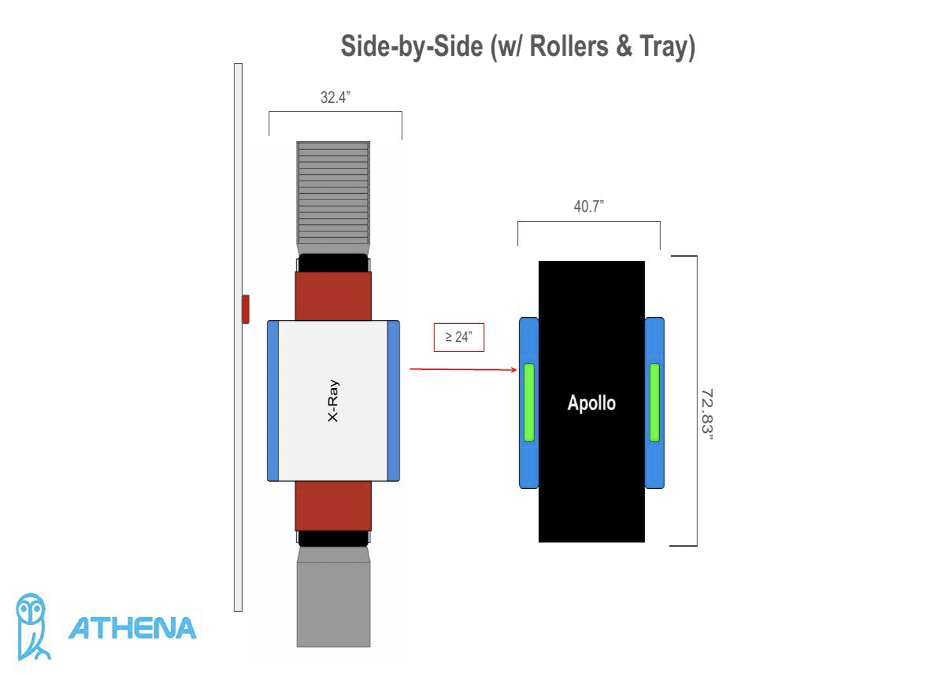
Figure 2 – Side-by-Side (w/ Rollers & Tray)
Configuration 2: Staggered Placement
In a staggered configuration, the Apollo is offset from the X-Ray (not directly beside it). This layout allows the Apollo to be positioned as close as 1 inch from the X-Ray, making it ideal for tighter spaces.
? In all staggered configurations, the X-Ray may be placed directly against the wall. The Apollo must remain at least 1" from the X-Ray.
Standard Staggered
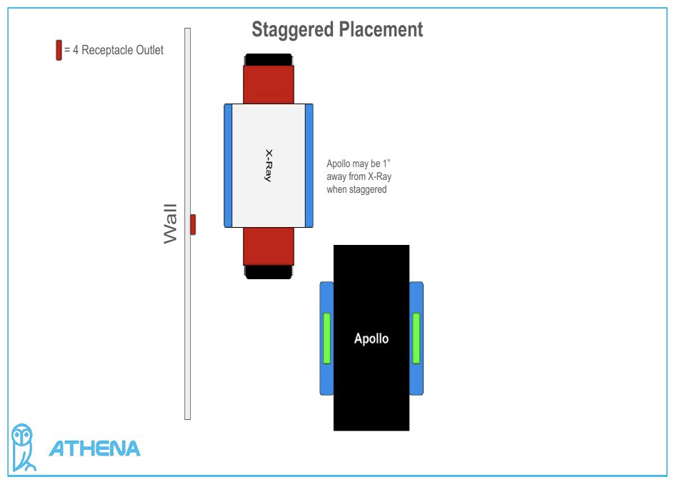
Figure 3 – Staggered Placement (Standard)
Against Wall (No Tray/Rollers)
The X-Ray can be pushed flush against the wall in this layout. The Apollo remains staggered and maintains the 1" minimum gap.
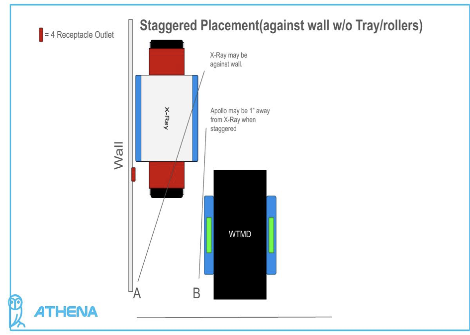
Figure 4 – Staggered (Against Wall, No Accessories)
Against Wall (With Rollers)
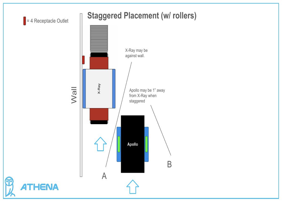
Figure 5 – Staggered (w/ Rollers)
Against Wall (With Tray)
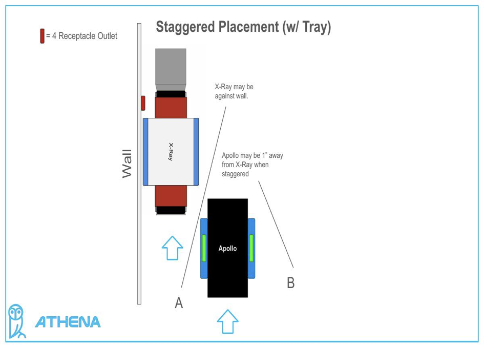
Figure 6 – Staggered (w/ Tray)
Against Wall (With Rollers & Tray)
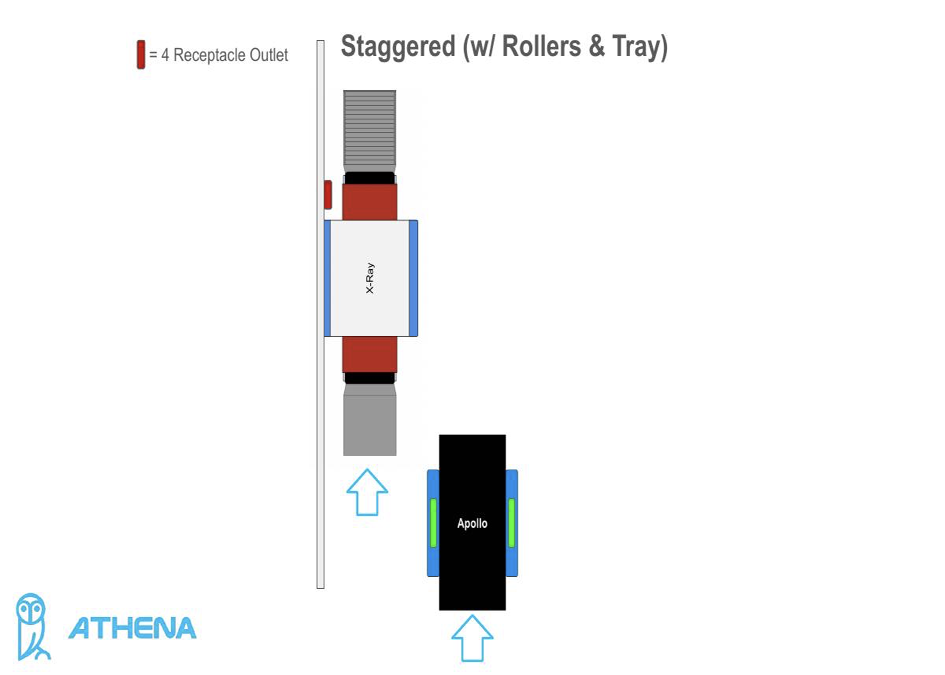
Figure 7 – Staggered (w/ Rollers & Tray)
Pre-Installation Checklist
Before placing your units, verify the following:
- Measure the total available floor space and confirm it meets minimum requirements for your chosen configuration.
- Locate and confirm the position of 4-receptacle outlets for both units.
- If using rollers or a tray, account for the additional depth on the X-Ray's input/output sides.
- For staggered placement, ensure there is at least 1" of clearance between the Apollo and X-Ray.
- For side-by-side placement, ensure at least 24" of clearance between units.
- Confirm the wall outlet is reachable from its marked position on the diagram (red indicator).
For installation support, contact Athena Security at supportwe@athenasecurity.com
Was this article helpful?
That’s Great!
Thank you for your feedback
Sorry! We couldn't be helpful
Thank you for your feedback
Feedback sent
We appreciate your effort and will try to fix the article